Introduction
A battery charger is basically a DC power supply source. Here a transformer is used to step down the AC mains input voltage to the required level as per the rating of the transformer.
 Working of Mobile Charger
- A bridge rectifier configuration is used to rectify the low voltage AC into DC and is further smoothed by a high value electrolytic capacitor.
- This DC is fed to an electronic circuit which regulates the voltage into a constant level and is applied to the battery under charge, where the energy is stored through an internal process of chemical reaction.
- In automatic battery chargers a voltage sensor circuit is incorporated to sense the voltage of the battery under charge. The charger is automatically switched OFF when the battery voltage reaches the required optimum level.
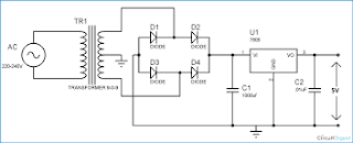
Circuit diagram

1.Step Down AC voltage
As we are converting 220V AC into a 5V DC, first we need a step-down transformer to reduce such high voltage to our required voltage.The voltage rating should be more than the required voltage.
2. Rectification
Rectification is the process of removing the negative part of the Alternate Current (AC), hence producing the partial DC. This can be achieved by using 4 diodes.
3. Filtration
The output after the Rectification is not a proper DC, it is oscillation output and has a very high ripple factor. We don’t need that pulsating output, for this we use Capacitor. Capacitor charge till the waveform goes to its peak and discharge into Load circuit when waveform goes low. So when output is going low, capacitor maintains the proper voltage supply into the Load circuit, hence creating the DC.
4. Voltage Regulation
A voltage regulator IC 7805 is used to provide a regulated 5v DC. Input voltage should be 2volts more than the rated output voltage for proper working of IC, means at least 7v is needed, although it can operate in input voltage range of 7-20V.
No comments:
Post a Comment